

HOW TO TEST AN OXYGEN SENSOR
There are two types of oxygen sensors: narrow band, and wide band. The narrow band will be 4 wires or less, while the wide band most of the time will be more than four wires. Today we’ll be focusing on the narrow band, specifically the zirconia type.
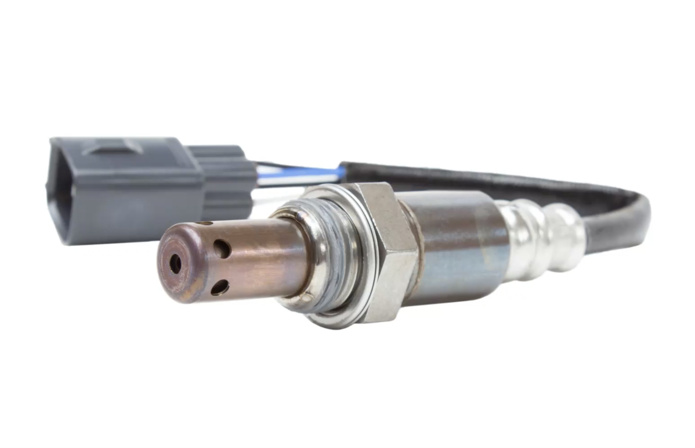
purpose & Location
The purpose of the oxygen sensor is to measure the amount of oxygen in the exhaust system and communicate it with the ECM. It does this by producing its own voltage by measuring the difference between oxygen in the atmosphere(back end of sensor or through the wire) and oxygen in the exhaust system (oxygen sensor head). It only produces a voltage when the sensor is heated up to 600°F. However, for faster and more efficient results it needs to be at 1500°F.
Most cars have two oxygen sensors: one before the catalytic converter, and one after. Some have three or even four depending on your engine size, or if you have two catalytic converters.
The oxygen sensor before the catalytic converter is used by the ECM to either add or reduce fuel by controlling the fuel injectors to achieve the perfect air-fuel ratio. For example, if the oxygen sensor measures a rich condition (above 0.45V or 450mV) which means more fuel and less air the ECM is going to reduce fuel. If the sensor measures a lean condition (below 0.45V or 450mV) which means more air, and less fuel the ECM will command more fuel. On the other hand, the oxygen sensor after the cat is used to calculate the efficiency of the catalytic converter.
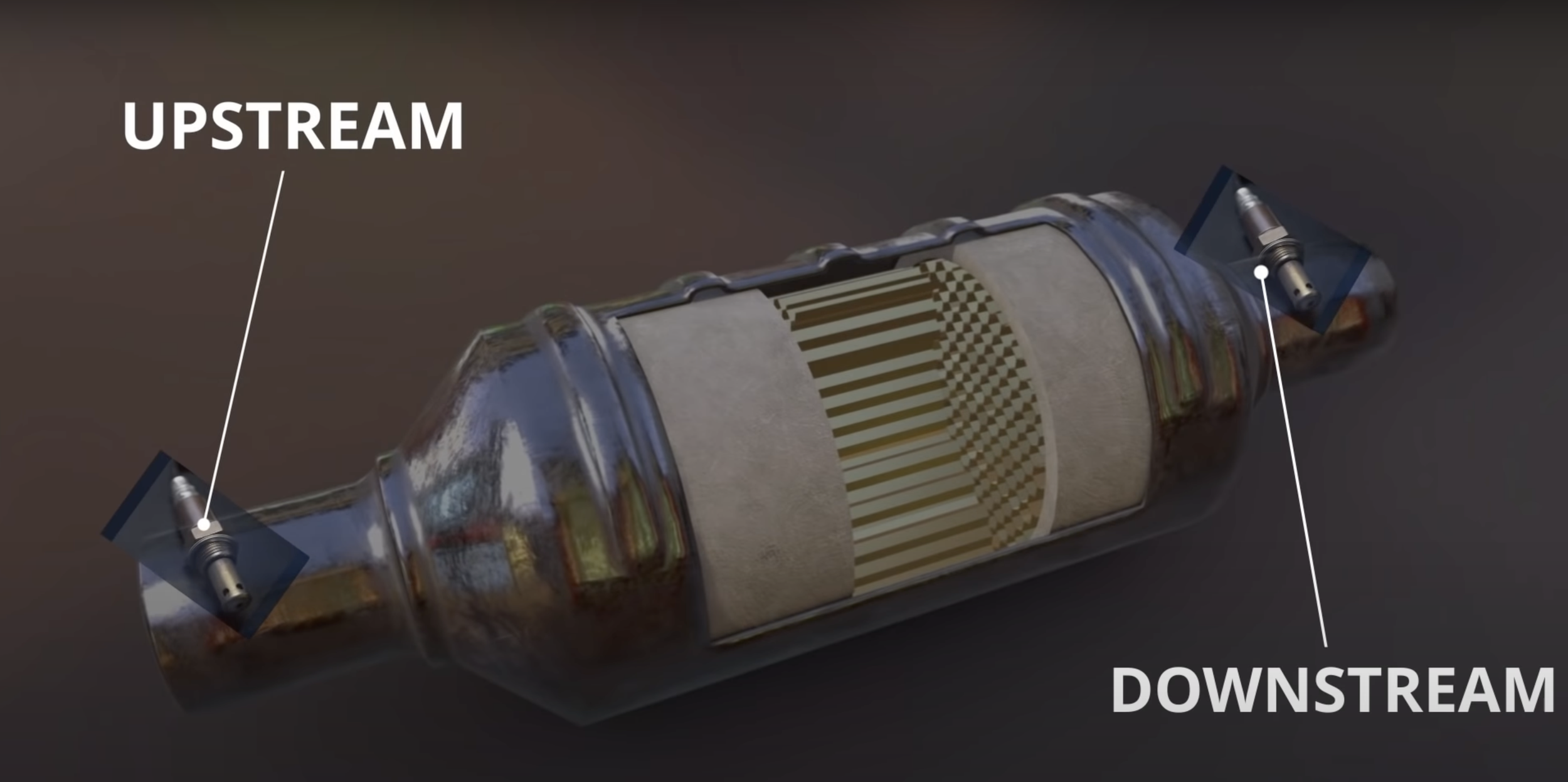
The location of the oxygen sensors.
There are four types of zirconia oxygen sensors:
One-wire (ground is through the threads of the sensor into the exhaust):
- Oxygen sensor signal
Two-wire:
- Oxygen sensor signal
- Oxygen sensor signal ground
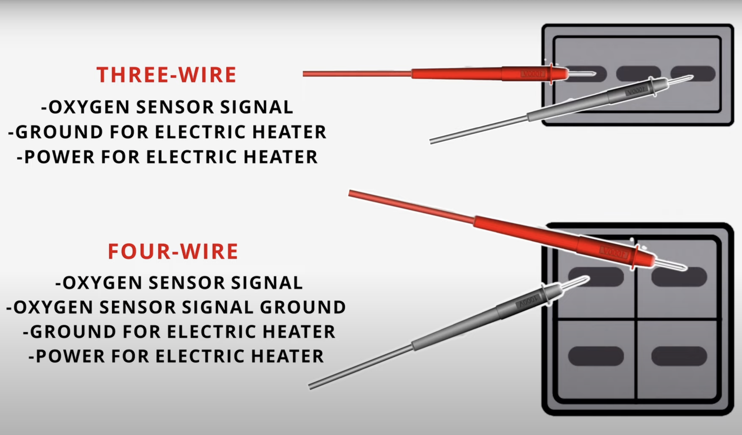
Three-wire (ground is through the threads of the sensor into the exhaust):
- Oxygen sensor signal
- Ground for electric heater
- Power for electric heater
Four-wire:
- Oxygen sensor signal
- Oxygen sensor signal ground
- Ground for electric heater
- Power for electric heater
TEST 1
We will start things off with the first test that can be applied to all four types of zirconia oxygen sensors. This test is only for the sensor before the catalytic converter (upstream). You’ll need a digital multimeter to perform this test. You can get my favorite multimeter here.
The first step is to ensure that your vehicle's engine is turned off before starting.
To test an O2 sensor, position your multimeter to 2 volts on the DC voltage section. Using a back probe test lead connect the red lead of the multimeter to the signal wire (usually black wire double check with your repair manual) of the oxygen sensor, then touch the black lead to solid ground. This can be the negative side of the battery or simply by touching the metal frame of the car. (Refer to the picture underneath step 7).
Now start your engine and wait until the oxygen sensor heats up to at least 600°F to be able to produce a voltage reading and allow the car to go into a closed loop.
Once your vehicle is in a closed loop, you want your voltage reading to fluctuate from below 300mV to over 800 mV, or below 0.3V to over 0.8V. If this is the case, your O2 sensor should be good and doesn't need to be replaced. If your oxygen sensor is malfunctioning and needs to be replaced, it won’t fluctuate at all or it will stay close to 450mV or 0.45V at all times.
If the O2 sensor reads higher than 550 mV at all times, this indicates a rich air-fuel mixture and could be caused by one of the following:
Leaking fuel injector
MAF sensor
ECT
Fuel pressure regulator
Purge valve
The high reading could also be caused by the sensor giving a bad reading due to contamination:
Engine oil
Silicone poisoning
Engine coolant
If you have a reading that’s below 350mV or 0.35V at all times, this indicates a lean air-fuel mixture and could be caused by a defective oxygen sensor or by one of the following:
Vacuum leak
Clogged fuel filter
Fuel pump
MAF sensor
Clogged fuel injector
Torn brake booster diaphragm
An easy way to check if the O2 sensor is faulty is to floor on the gas pedal. You should see the O2 sensor react instantly and increase voltage. If it doesn’t, then most likely the oxygen sensor is bad.
How to connect the multimeter to test an O2 sensor and the battery.
test 2
The second test only applies to the oxygen sensors with the heater (3 wire & 4 wire) and can be used for both sensors before and after the catalytic converter.
First, make sure the vehicle is off. You want to set your multimeter to 200 in the Ohms position to measure resistance.
Next, disconnect the oxygen sensor and connect one test lead to the heater terminal while connecting the other lead to the second heater terminal. (Refer to the picture underneath Step 4). On most cars, the heater wires will be the same color but make sure by looking into your vehicle’s repair manual. If you don’t have one, I would recommend buying this repair manual. They are very simple and easy to follow (use code “AD10VA” for 15% off one-year subscriptions for any US order).
If you get no reading at all, then you have a bad heater and the sensor needs to be replaced.
If you do have a reading, then that’s a good sign, just make sure it’s within specifications according to your vehicle’s repair manual. I’ve seen specifications being from 2-4, 5-7, and even up to 16 Ohms.
Make sure you check your wires are not damaged and the connectors are free of corrosion as these can make your oxygen sensor malfunction.
Check out my YouTube video!
Disclaimer: Some links in this article may be affiliate links.